a – OCSiAl Group, 1, rue de la Poudrerie, 3364 Leudelange, Grand Duchy of Luxembourg
b – Department of Chemistry and Biochemistry, New Mexico State University, Las Cruces, NM 88003, United States
c – NM Devices, LLC, 690 Canyon Point, Las Cruces, NM 88011, United States
In the first part [1] we discussed the structural and physicochemical properties of single walled carbon nanotubes (SWCNTs) with the emphasis on TUBALLTM produced by OCSiAl. This part focuses on the applications of Tuball capitalizing on its unique properties. We start with discussing the methods for dispersing SWCNTs in various media suitable for maximizing their positive effect on the mechanical, electrical, and other functional properties of the composites. It follows by the examples of applications of Tuball in materials for batteries, thermosets, thermoplastics, and elastomers, most of which employ commercially produced liquid and semisolid dispersions offered by OCSiAl. This demonstrates the real versatility of Tuball augmentation for improvement of electrical and mechanical properties of various materials and should stimulate its wide application.
The trade name “TUBALLTM graphene nanotubes” or just Tuball was chosen to emphasize its distinction from other SWCNTs that were on the market at the time. In its purified form, Ultrapure Tuball, it has below 1% of impurities. Currently, a significant portion of the world market of SWCNTs is estimated to be held by Tuball (in excess of 60 tonnes annual production or over 90 % of the world production capacity) and its industrial applications have risen significantly as a result in recent years. In Fig.1 of Part 1 [1] we have illustrated a broad application of Tuball nanotubes by the rising number of publications employing it. Similarly broad is its commercial application. A search in the professional patent database PatSnap for the term "Tuball" in the description of the invention yields 344 documents in 165 patent document families as of February 18, 2022, with 139 families being published within last 2 years. Usually, the brand name or trademark of the material is mentioned in the description of a patent when this material has been used for the experimental confirmation of the industrial applicability of the invention. We have illustrated in [1] via a brief literature review that employing Tuball imposes minimal health risks. The conclusion was confirmed by registering Tuball brand in accordance with the European Union REACH regulation, permitting its broad production and utilization at industrial volumes in Europe.
The unique physical properties of single walled carbon nanotubes (SWCNTs) in electrical conductivity, mechanical strength, high surface area, and others provide a broad spectrum for their applications in composite materials as a versatile filler. A significant effect of Tuball filler can be achieved when the nanotubes are well dispersed and can form a specific three-dimensional network suitable for maximal performance [2-5]. The ideal dispersion of SWCNTs in an arbitrary matrix is extremely difficult to achieve. Due to a strong π - π interactions, the SWCNTs are typically aggregated into bundles, and, as can be seen from the TEM in Fig. 2 of Part 1 [1], this is also true for Tuball SWCNTs. These bundles branch, merge, and form agglomerates of complex topology. To fully capitalize on the Tuball augmentation in improving new composite materials, it is necessary to separate nanotubes into individual ones or into suitable bundles and provide the means of stabilizing them in such state. In the following sections, we examine various methods of dispersing SWCNTs and how that improves the functional properties of augmented by Tuball nanocomposite materials including electrical and mechanical properties.
Effective dispersion of single walled carbon nanotubes in the liquid phase is a crucial processing route required for many applications. Although there are some liquids where SWCNTs can be considered slightly soluble [6-10], the solubility is limited, well below of the practical interest and the solvents are relatively expensive/ incompatible with commercial applications. According to [6,7] the solubility of SWCNTs in some pyrrolidones is significantly greater than in other solvents due to closeness of Hansen solubility parameters (HSP). The estimated Hansen parameters for dispersion (δD), polar (δP), and hydrogen bonding (δH) of SWCNTs (HiPCO) are close to those of cyclohexyl pyrrolidone (CHP) with the corresponding highest solubility of SWCNTs in it (3.5 mg/mL), see Table 1. Other pyrrolidones, N, N′-dimethylpropyleneurea (DMPU) and N-methylpyrrolidone (NMP) have less matching of HSP and noticeably declining SWCNT solubility, which is still higher than in dimethyl formamide (DMF) and isopropanol (IPA). The HSP distance between two substances, Ra² = 4(δD1-δD2)² + (δP1-δP2)² + (δH1-δH2)², can be used to quantify the closeness and Table 1 illustrates a strong correlation of the solubility with Ra2.
Table 1. Hansen parameters of SWCNTs (HiPCO) and some solvents along with the SWCNT solubility in them [7].
Substance | δD | δP | δH | SWCNT Solubility, mg/mL | Ra² |
SWCNT (HiPCO) | 17.8 | 7.5 | 7.6 | ||
CHP | 18.2 | 6.8 | 6.5 | 3.5 | 2.34 |
DMPU | 17.8 | 9.5 | 9.3 | 0.65 | 6.89 |
NMP | 18.0 | 12.3 | 7.2 | 0.116 | 23.4 |
DMF | 17.4 | 13.7 | 11.3 | 0.023 | 52.8 |
IPA | 15.8 | 6.1 | 16.4 | 0.0105 | 95.4 |
Charging SWCNTs via the reduction or oxidation can also facilitate their dissolution in polar solvents [8-11]. For example, charging SWCNTs positively can be achieved via associative protonation with superacids, such as oleum or chlorosulfonic acid (CSA) [8-10], but the superacids are hard to work with in industrial settings due to their sensitivity to water and safety concerns. The negative charging of SWCNTs can be realized using reduction by metals [8,10,11], but due to sensitivity to oxygen, industrial realization of this technique is also problematic. Thus, dispersing SWCNTs with the help of coating surfactant molecules and soluble polymers is the most viable at the moment.
According to the theoretical estimates [12,13], the π−π binding energy between the neighboring SWCNTs is on the order of 1 eV per nanometer of nanotube length. For the bundles of several microns long comprising thousands of nanotubes, this binding energy can exceed several MeV per bundle, which is the mechanically imparted energy that would be required for separating them. Different methods of mechanical agitation for dispersing SWCNTs have been explored and there is no universal one suitable for all systems [2-5]. The methods should be tailored based on the system’s viscosity, the type of matrix that affects the strength of interaction with SWCNTs, and the type of dispersing agent.
One effective way of dispersing SWCNTs in liquid solutions involves ultrasound irradiation with surfactants/dispersants, which suppresses reagglomeration of SWCNTs. Cavitation created during ultrasound irradiation achieves significant shear stress near bundles to induce their disassembly. The surface of newly detached nanotube gets coated with the surfactant molecules and thus hinders the process of reverse agglomeration [15,16]. Increasing the total energy of ultrasonic irradiation unzips the bindles and coats SWCNTs with dispersing agent/surfactant bringing the system towards thermodynamic equilibrium (see Fig. 1), which depends on the SWCNT concentration and the type and concentration of the dispersing agent. According to [15], the dispersants can be divided into two categories: dynamic (small molecules) and static (polymers). For the latter case, the non-covalently bound polymers wrap around CNTs and remain even after the washing process, such as filtration, to provide the ‘polymer-wrapped CNTs’. Both types of dispersants require mechanically induced disassembly of bundles, such as via ultrasonic treatment.

Fig. 1. Schematic illustrations for the dynamic (upper) and static (lower) dispersion of CNTs. Adapted with permission from [15].
However, the side effect of such ultrasound treatment is that it not only splits the bundles apart, but, unfortunately, some damage occurs as well -- from the formation of defects to cutting nanotubes and bundles into shorter fragments [16-21]. Due to that, the power and time of sonication needs to be limited. Thus, there is an optimum when the sonication is sufficient to produce a good dispersion and, the same time, the damage is minimal. The outcome and the optimum amount of input energy depend on the solvent and dispersant, with obvious distinction between the small molecule amphiphiles and longer polymeric molecules. From the experimental estimates it appears that for dispersing ~ 0.1% (by weight) SWCNTs into a stable suspension of individual nanotubes and thin bundles, it is necessary to invest more than 1 kWh or 3.6 MJ of energy per liter of solution. All amounts in % here and later will refer to weight % (wt%), unless explicitly mentioned otherwise.
For obtaining pure dispersions consisting of individual nanotubes and the thinnest bundles, the dispersions are subsequently cleaned from the remnant large bundles and agglomerates by sedimentation separation using an ultracentrifuge. The dispersions obtained this way can remain stable for several weeks, and some can be stable practically indefinitely. The stability depends on the nanotube concentration and the type of dispersant. For commercial production of dispersions, one has to deal with > 0.1 % of SWCNT dispersions and the optimization of such concentrated dispersions becomes an issue. It is more effective when the preliminary homogenization of SWCNT agglomerates along with dispersant using a high-shear rate mixer precedes the ultrasound homogenization (see, for example, [22]). The preliminary homogenization step expedites the ultrasonic treatment by untangling nanotubes and bundles, which significantly improves the quality of the dispersions in less time and more cost effectively. The quality of the obtained dispersion can be controlled by optical microscopy, NIR-Vis spectroscopy [23], via monitoring the optical density of the dispersions and their stability to sedimentation [24].
Figure 2 a-b shows the evolution of the optical density in 0.2% aqueous dispersions of Tuball with 0.3% of carboxymethyl cellulose (CMC) dispersant, which was monitored by diluting it to 0.001% for convenient measurement in 1 cm cuvette. The stability of solutions was evaluated as the remaining fraction of the optical density of a dispersion after centrifugation at 8000g for 40 min.

Fig. 2. Evolution of the optical density at 500 nm with ultrasound irradiation time for aqueous dispersions of: a) 0.2%Tuball/0.3% CMC (carboxymethyl cellulose, black) and 0.2% Ultrapure Tuball /0.3% CMC (red), d) 0.2%Tuball/0.4% PVP (polyvinylpyrrolidone, black) and 0.2% Ultrapure Tuball /0.4% PVP (red), all diluted to 0.001% concentrations before measuring optical density; b, e) Sedimentation stability of the same dispersions after centrifugation at 8000g for 40 min; c, f) Viscosity of the same dispersions at shear rate 18.6 s-1.
As the ultrasound energy increases, the optical density of a dispersion increases and eventually reaches plateau corresponding to stable dispersion. It appears that the purified Ultrapure Tuball is more difficult to separate into individual nanotubes, although the final optical density for it is higher than that for the original Tuball, in agreement with a smaller amount of impurities in Ultrapure Tubal. Similar results were previously reported for aqueous dispersions of HiPCO nanotubes [24]. The presence of impurities (e.g., catalyst nanoparticles) hinders alignment and decreases the contact area between SWCNTs (compare Figs. 5 and 8 from Part 1 [1]) thus making it easier to separate them. The difficulty of dispersing SWCNTs is the price to be paid for the improved purity of nanotubes.
Stability of a dispersion towards sedimentation characterizes the distribution of bundle sizes and their interaction, which is hard to identify optically. As the energy invested in the dispersion increases, the thickness of the nanotube bundles decreases and a greater number of individual nanotubes appear in the dispersion, thus increasing its stability. The dispersions with purified nanotubes also have less stability compared to the untreated ones, which also corroborates that the purified nanotubes are more difficult to disperse and require more energy to produce dispersions of a similar quality.
The dispersions with polyvinylpyrrolidone, PVP (k30), dispersant behave similarly, as shown in Fig. 2 d-e. Note that the PVP based dispersions have higher stability, which indicates that more individual nanotubes and thin bundles are present in them.
The viscosity behavior of such SWCNT dispersions is non-Newtonian, it depends on the shear rate (suspensions are shear thinning or pseudoplastic) and on the history of the applied shear (they are thixotropic). Typical dependence of the viscosity on the shear rate follows Ostwald-de Waele power law [25] as illustrated by Fig. 3:
μ=K(n-1) (1)
Here is the dynamic viscosity, is the shear rate, and n is the flow behavior index, n < 1.

Fig. 3. Effect of the shear rate on the viscosity of 0.3 % Tuball water dispersion with 0.6 % of PVP as dispersant.
At rest, or at low shear rates, the SWCNTs build-up a network of physically entangled bundles that gives a high viscosity to solution and dispersion gradually over time becomes a gel. The longer the Tuball Batt H2O stays at rest, the higher the viscosity it gains. Typical kinetics of gelation are shown in Fig. 4. Obviously, a gel of SWCNTs is stable to sedimentation and can be preserved it that state for a long time. Nevertheless, after a shear is applied, this network of physically bound bundles can be broken down leading to the viscosity decrease -- the suspension becomes degelated. It doesn’t matter how long the suspension had been at rest before degelation, its viscosity after degelation is the same every time. However, it may take more than several minutes to break the network down completely. The higher is the shear rate, the faster is the breakdown process. Any Tuball suspension still obeys the power law of Eq. (1) (see Fig. 4B), but the flow behavior index for degelated Tuball suspension is higher and it is closer to the Newtonian liquid. Simultaneously, the flow consistency index, K, diminishes (see Fig. 4C, D) following its own power law (2), leading to a less viscous state of SWCNT suspension:
K=K0n-3.3 (2)

Fig. 4. A. The effect of storage on the viscosity (gelation). B. The effect of mechanical mixing (circles) and ultrasonic treatment (triangle) on the viscosity-shear rate plot of initially gelated suspension of 0.2 % Tuball SWCNTs with 0.3 % CMC in water. C. Correlation of the Ostwald-de Waele parameters for the same suspension. D. The same plot in log/log coordinates with additional data for 0.2 % Tuball /0.4 % PVP in water (triangles). The arrow denotes the initial gelated state for which the effect of shear rate on viscosity is shown in Fig. 4B.
Evidently, it is difficult to use the viscosity of Tuball suspension as an unambiguous indicator of the SWCNT dispersion quality since it is sensitive not only to the concentration, diameter, and length of the dispersed SWCNTs, but also because their interactions can cause formation of bundles and agglomeration, i.e., the viscosity is also sensitive to the dispersant and the quality of dispersion.
We chose a representative shear of 18.6 s-1 and will refer to the value of viscosity at that point as ‘viscosity’. Evolution of the viscosity of the CMC and PVP based dispersions of Tuball with ultrasound energy is shown in Figs. 2 c and f. The behavior of dispersions with Tuball and Ultrapure Tuball is very different. In the former, the viscosity initially rapidly increases to its maximum value and then monotonously decreases with the ultrasound energy imparted on the dispersion, while in the latter the viscosity is substantially lower and evolves more gradually. We suppose that this effect is due to a different structure of initial bundles for Tuball and Ultrapure Tuball. Agglomeration of SWCNTs in a CVD reactor happens in a flow and thus promotes formation of long bundles that are highly interconnected. Their disassembling initially produces long and relatively thin individual bundles increasing concentration of which raises the viscosity. Deaggregation of these bundles with further treatment makes them shorter and lowers the viscosity. Purified nanotubes Ultrapure Tuball that had numerous stages of washing after removal of the catalyst are aggregated into thicker more parallel bundles. The process of their dispersion does not go through the stage with long thin bundles but approaches the same value at longer times of irradiation.
Dispersing SWCNTs using ultrasound is effective only for relatively low concentrations < 0.2%. A higher viscosity at greater concentrations of nanotubes sharply decreases the efficiency of the above technique due to unproductive mixing near the ultrasound horn, even with enforced circulation, and the ultrasonic energy is spent mainly on heating.
At higher concentrations, other dispersion methods are more useful, in which the dispersion occurs due to more effective impacting the shear forces on the medium. The shear force, η, that occurs in a viscous medium is proportional to the shear rate, τ, and viscosity, ν: η ~ τν and, therefore, the dispersion efficiency should increase with viscosity. For good dispersions with nanotube concentrations above 0.2%, when the use of ultrasound becomes ineffective, a high-pressure homogenizer or HPH (like used here Microfluidics M-110P) becomes quite efficient.
As Fig. 5 illustrates, the stable dispersions with 0.2% and 0.4% Tuball with CMC as a dispersant, can be effectively produced using HPH. The optical density, stability, and viscosity rise with the number of passes very efficiently. Note that the dispersion with 0.2 % has a similar behavior. Actually, the higher viscosity at a higher nanotube concentration makes the dispersion process more efficient as judged by their stability.
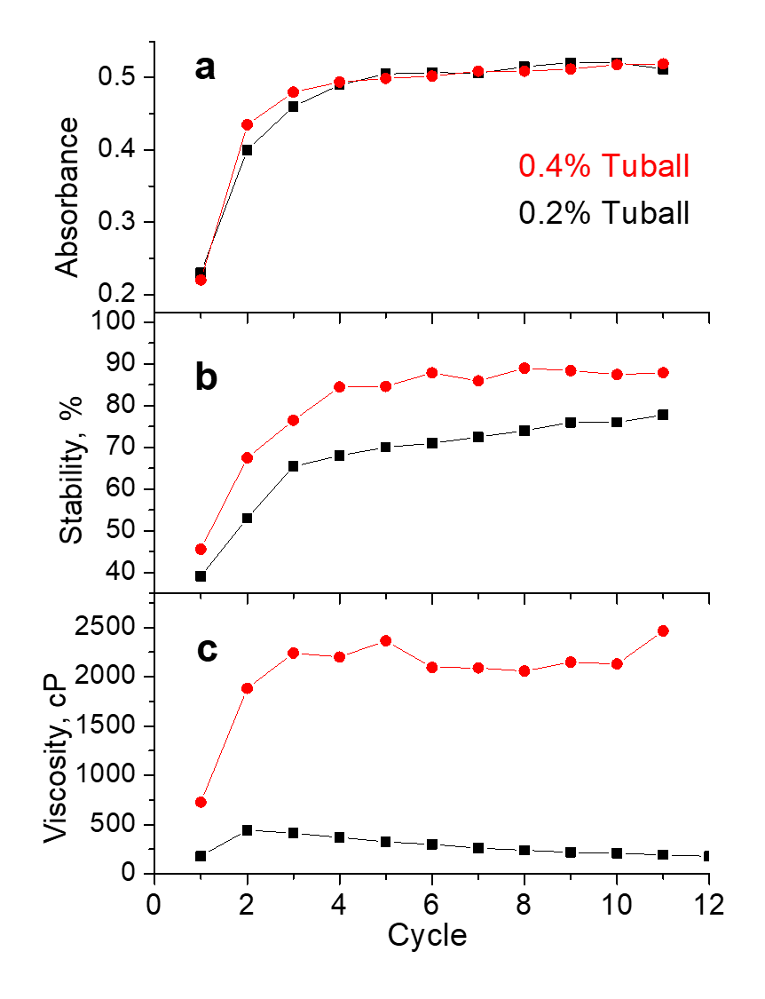
Fig. 5. Evolution with the number of cycles on high-pressure homogenizer, HPH, for the optical density (a), stability after centrifugation at 8000g for 40 min (b), and viscosity (c) at 18.6 s-1 in 0.2%Tuball/0.4% PVP (black) and 0.4% Tuball/0.8% PVP (red) dispersions. Optical density was measured in solutions diluted to 0.001% concentrations.
The use of HPH for nanotube dispersion is limited to a relatively narrow concentration range due to the rapid increase in the dispersion viscosity with increasing the nanotube concentration. At viscosities exceeding 20 P, the friction during forcing the dispersion through a narrow capillary becomes prohibitively high causing an excessive local overheating in the dispersion zone. The ultimate viscosity of a dispersion that can be prepared using this technique is determined by the properties of the dispersant and the Tuball / dispersant ratio. For aqueous dispersion with CMC, where the standard concentration ratio is [Tuball]/[CMC] = 2/3, the Tuball concentration range suitable for this method is 0.1-0.8%. The viscosity in the dispersions of Tuball with CMC, shown in Fig. 6, has a very strong dependence on the Tuball concentration, η ~ [Tuball]3.4.

Fig. 6. Viscosity variation with the Tuball concentration for its aqueous solution prepared using HPH with 1.5 times amount of CMC. On the right is the optical microscope image of 0.4% dispersion diluted 40 times illustrating a perfect quality of homogeneous dispersion. Scale bar is 50 μm.
There are different commercially available dispersions produced by OCSiAl and listed in Table S1. The list is evolving due to the market’s demands, but the majority of positions have remained for quite some time. A major commercial application is in batteries, some of which is discussed below, but other applications have been emerging and we hope that new applications will be identified in a near future. Because of the strict requirements, the dispersions for batteries (named Tuball Batt) are made from purified Ultrapure Tuball and are free of metal impurities. They include aqueous solutions with polymeric dispersants such as polyvinylpyrrolidone (PVP), carboxymethyl cellulose (CMC), polyacrylic acid (PAA), and N-methyl pyrrolidone (NMP) solution with poly(vinylidene fluoride) (PVDF). For non-battery applications, like conductive coatings and others, aqueous dispersions with small molecule dispersants are recommended including sulfanol, leukanol, and sodium dodecylbenzenesulfonate. Such dispersants can be removed after deposition.
One of the applications for SWCNTs is in the battery electrode materials, for which the above-described liquid dispersions represent the convenient intermediate product. The presence of nanotubes in the electrode matrix can compensate for alterations of structural integrity and improve the electrical conductance in the electrode. Significant volume changes due to charging-discharging lead to accelerated electrode degradation which the nanotubes can slow down by literally holding the pieces together. Due to their high conductance, carbon nanotubes also improve the electronic transport in the nanostructured electrodes beyond what the traditional carbon conductive additives can offer.
The efficient modification of electrode material strongly depends on the means of introducing nanotubes into the electrode matrix and it should be achieved without changing the technological process. Adding well dispersed CNT slurry satisfies these requirements and allows obtaining high conductive characteristics of the electrode with a low Tuball content. Since it is important to have no metallic impurities, such dispersions (labeled appropriately as Tuball batt) are produced with Ultrapure Tuball, but for simplicity will be referred to as just Tuball. Lithium Nickel Manganese Cobalt Oxide (or just NMC) batteries represent a broad subclass of Li-ion batteries with different stoichiometries of Ni, Mn, and Co. Figure 7 shows how the resistance of NMC111 (or LiNi1/3Mn1/3Co1/3O2) cathode changes with the addition of Tuball instead of the standard conductive additive SuperP carbon black. The graph shows that in the range of 0.02-0.06 % Tuball concentrations, a percolation transition is achieved leading to the formation of a conducting network of nanotubes and at 0.04 % the electrode resistance is comparable with that for 2.5% of standard conductive additive SuperP. Further increase of Tuball concentration to 0.06 % drops the electrode resistance to over 4 times lower than that with SuperP. Such minute concentrations require very uniform distribution of the dispersed nanotubes over the entire volume of the electrode material for the ultimate performance, which can be achieved only with a high quality of the dispersion and its subsequent homogenization with the electrode paste after.

Fig. 7. Resistivity of NMC111 cathode for different fraction of Tuball composition NMC/PVDF/Tuball : 99-х/1/х (blue) and its value for NMC/PVDF/SuperP : 96/1.5/2.5 (red).
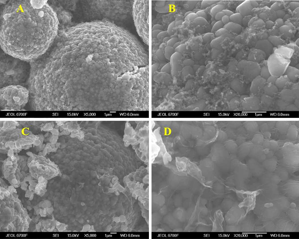
Fig. 8. SEM images of NMC811 cathodes: A-B) 1.5% SuperP without Tuball and C- D) 0.08% Ultrapure Tuball without SuperP. In all cases the scale bar is 1 μm.
SEM images in Fig. 8 compare the SWCNT based NMC811 cathode materials with that for the standard conductive additive. The standard conductive additive, carbon black SuperP, widely used in the Li-ion batteries, is here in the 1.5 % amount and is evenly distributed over the surface of NMC811 particles as recognizable agglomerates with empty voids ~ 0.5 μm in size. The cathode particles’ surface in Figs. 8 C-D with 0.08% Tuball as the carbon additive are more evenly wrapped around by a web of dispersed carbon nanotubes, which uniformly cover the material without any “blind zones”.
The SWCNT based formulations have been successfully used in a number of studies, some of which are published. Wu et al. [26] demonstrated that in ultrahigh-areal-capacity SiOx anodes for lithium-ion batteries, employment of SWCNTs (realized through using Tuball Batt NMP, i.e., solution in N-methyl pyrrolidone) significantly improved their cycling stability. As Fig. 9a illustrates, composite coating of SiOx with SWCNTs/Super P atop of carbonized SiOx, i.e., SiOx@C@P_CS, exhibits Coulombic efficiency ~99.9% and 86.7% capacity retention (1.02 Ah/g) after 1000 cycles at 0.75 A/g, much better than without SWCNTs. Even at the rate as high as 4C the capacitance is close to 0.75 A·h/g, as can be seen from Fig. 9b.

Fig. 9. a) Electrochemical performance of the SiOx, with carbon coating, SiOx@C, and with additional coating with SWCNTs and SuperP, SiOx@C@P_CS, as the cycling at 0.5C; b) the rate capabilities at various rates from 0.2 C to 4C for the same anode materials, SiOx@C@P_CS and SiOx@C electrodes at 0.5C for 200 cycles, respectively. Reprinted with permission from [26].
Shenzhen BAK Power Battery Co (from China) has successfully employed the SWCNT based formulations in the development of new Li ion batteries. The positive effect was observed for addition of SWCNTs via Tuball Batt suspension into both, cathode and anode. Figure 10 illustrates such a positive effect for the cathode. Compared to the standard SuperP additive, introduction of SWCNTs improves the charge/discharge capacity in the first cycle, as well as the aging stability. The Coulombic efficiency of the first cycle also improves.

Fig. 10. NCM811 cathode performance comparison with different additives. A) Fist charge-discharge capacity with SuperP vs Tuball SWCNT (SP-F&SWCNT-F) formulations for 0.2C charging current to 4.2V and cut off current: 0.01C; end-of discharge voltage 2. 5V. Charge-discharge after aging for 0.2C (SP-0.2 & SWCNT-0.2) and 0.5C (SP-0.5 & SWCNT-0.5) for the same formulations. B) First Coulombic efficiency for the same formulations. Courtesy of Dr. Jian Lin, BAK Power Battery Co., Ltd.
Similarly, Fig. 11 illustrates the effect of Tuball for the SiOx anode, where introduction of SWCNTs improved the cycling performance of SiOx compared to the standard SuperP additive. Moreover, the effect was more pronounced at the higher silicon content.

Fig. 11. Comparison of conductive additives in SiOx anode of NCM811 cell. Capacity fading for cycling at 0.5C to 4.2V and discharging at 1C to 2.75V. Addition of SWCNTs into anode improves the cycling performance of SiOx. Courtesy of Dr. Jian Lin, BAK Power Battery Co., Ltd.
Positive effect from using Tuball in NMC811 (LiNi0.8Mn0.1Co0.1O2) batteries has been also reported by Coleman’s group [27]. The composite battery electrodes of NMC filled with Tuball SWCNTs showed significant electronic improvement for both, in-plane (σIP) and out-of-plane (σOOP), conductivities. The latter is ~1000 lower than that in-plane. The loading level required to achieve sufficient electronic conductivity strongly varied with the filler type and Tuball showed the greatest efficiency compared to carbon black and graphene, as seen in Fig. 12.

Fig. 12. In-plane (IP) and out-of-plane (OOP) conductivities of composite electrodes based on NMC811 filled with various conductive fillers: carbon black (A), graphene (B), and Tuball carbon nanotubes (C). The dashed lines represent percolation fits and the solid lines - estimated fits with the effect of contact resistance removed. (D) Ratio of the in-plane to out-of-plane conductivity plotted versus volume fraction. Reproduced with permission from [27].
The beneficial use of Tuball nanotubes as a conductive additive was also demonstrated in the lead-acid batteries. Figure 13 illustrates that addition of SWCNTs (using Tuball Batt H2O PVP) improved the cell performance more efficiently than MWCNTs. Cells with the standard carbon material lasted only 200 cycles while adding 0.01 % of MWCNTs (from Hongwu Nanometer Inc., China) into either positive (PMWCNT) or negative (NMWCNT) electrodes noticeably improved the performance. Splitting the nanotubes between both electrodes (PMWCNT cell) made the effect more pronounced but using SWCNTs (Tuball) instead additionally doubled the effect corresponding to ~ 4.7 times improvement compared to the standard recipe [28,29]. SWCNTs were introduced into the active electrode materials via aqueous Tuball Batt CMC and PVP, respectively.

Fig.13. Cycle-life data for lead-acid cells at 25% depth-of-discharge (DOD) operation containing (a) SWCNTs and (b) MWCNTs: 0.01% of CNTs was added either to positive electrode (PSWCNT and PMWCNT cells) or negative electrode (NSWCNT and NMWCNT cells) or both with the balanced capacity (SWCNT and MWCNT cells). Reproduced with permission from [28].
The same group further found the optimized doping levels of SWCNTs at 0.01% and 0.001% for the positive and negative electrodes, respectively, and the corresponding 0.05% and 0.01% optimal doping levels for MWCNTs. Figure 14 shows that cycling of the cells with silica gel-type electrolytes at 25% and 50% depth-of discharge (DOD) is far more efficient for the cells with SWCNTs -- the service life of ~1,700 and ~1,400 cycles for 25% and 50% DOD operations, respectively, much greater than 950 and 830 cycles for the MWCNT based cells and only 360 and 270 for the standard cells.

Fig. 14. Life-cycle data for 2 V gelled electrolyte lead-acid cells with and without CNT additives under 25% and 50% depth-of-discharge (DOD) operations. Reproduced with permission from [29].
The base recipe used in our analogous studies of lead-acid batteries showed better cyclability, ~ 450 cycles, of the base recipe, as presented in Fig. 15. Nevertheless, even there, introduction of 0.01% Tuball via Tuball Batt CMC into the positive electrode increased the battery life by ~ 3.7 times, in agreement with the cycling data for cells with the modified positive electrode (PSWCNT) in Fig. 13a.

Fig. 15. The cycling data for lead-acid cells containing no SWCNTs (blue) and 0.01% SWCNTs (red).
In the previous sections we examined some methods of dispersing SWCNTs in solutions using dispersing reagent. In many applications similar methods can be used to introduce SWCNTs into polymeric materials to improve their functional properties including electrical conductivity and mechanical strength/modulus, but the choice of a dispersant, if any, must be tailored to a particular application. The solution approach can be realized if SWCNTs (with and without a dispersant) and a polymer can be simultaneously dissolved in the same solvent. We will demonstrate some examples of that below. SWCNTs can also be deposited on the solid surface of polymer granules or powder from solution with subsequent elimination of the solvent, but this approach is limited to quite low concentrations of SWCNTs. Alternatively, SWCNTs can be dissolved in liquid monomer which after subsequent polymerization produces solid solution of SWCNTs in the polymer.
A more convenient general approach that can be applied to a broad class of polymers is based on using concentrates of SWCNTs in a suitable high viscosity or low melting temperature dispersant/carrier. Such highly concentrated (2-25% of Tuball) modifiers are produced either on a three roll mill (3RM), ball mill, bead mill, or planetary mill [30]. It allows partially break the bundles of SWCNTs by forcing the dispersant molecules in between and brings the versatility of choosing optimal carrier complementary to the desired system. The main purpose of such modifiers, which we call Matrixes, is to introduce the electrical conductivity in otherwise dielectric materials by augmenting small concentrations of Matrixes. OCSiAl offers a variety of Matrix modifiers, majority of which are list in Tables S2, S3, and S4. They are divided into three categories for recommended use in thermosets, in elastomers, and in thermoplastics, respectively. A more detailed itemization in each category is based on internal and external evaluations and reflects often encountered countereffects (outside the recommended use) when the positive effect on the conductivity is accompanied by a negative impact on the mechanical properties. Nevertheless, it is common that both, electrical conductivity and mechanical properties are enhanced by small amount of added Matrix concentrate and different Matrixes can work well in multiple systems.
We will start by discussing what one should expect for electrical conductivity and mechanical properties from augmenting with SWCNTs.
The unique physical properties of SWCNTs -- electrical conductivity, high mechanical strength and modulus, high surface area -- provide a great range for applications in composite materials as a versatile filler. Obviously, a significant effect of such filler can be achieved when the filler particles form a three-dimensional percolative network [31]. For electrical conductivity of a material, the network of connected and uniformly distributed SWCNTs in a composite matrix provides direct charge transfer and the electrical conductivity intrinsically depends on the topology of the percolation network. The influence of SWCNTs on the mechanical properties is more convoluted: in addition to direct reinforcement by the network of SWCNTs, the presence of filler particles changes the viscosity of the polymer melt and its crystallinity upon cooling, Many effects are manifested even when the SWCNTs do not form a connected grid in the composite, but a percolation network is necessary to achieve the maximum conductance.
In the case of a uniform and isotropic distribution of a filler, the formation of a percolation network requires that its content exceeds the critical value, called the percolation threshold, fc. Above the percolation threshold, the conductive network grows according to the Kirkpatrick power law with power dependence of the conductivity [32]:
σ ∝ σc(f - fc)t, (3)
where the content is measured in volume fraction, f, and the exponent, t, for a model of isotropically and homogeneously distributed hard filler particles is ca. 1.94 for a three-dimensional network and ca. 1.33 for a two-dimensional case. With the filler concentration declining below the percolation threshold the conductivity drops to zero and the concentration of connected pathways linking chosen regions, S, decreases very fast:
S ∝ Si(fc - f)-s, (4)
where the exponent, s.
A key advantage of SWCNTs compared to all other fillers (including MWCNTs, graphene oxide, and other nanoscale fillers) is a very low percolation threshold. This is because the percolation threshold depends on the shape of the filler particles, mostly their aspect ratio, A = L/d (length over diameter). Several theoretical models for evaluating the dependence of fc on A [33-35] lead to the relations of a general form given by Eq. (5):
fc = k/(A)b (5)
where the factor k includes the ordering parameter, and the exponent b varies between 0.8 and 2, depending on the specific assumptions. In particular, the stiffness of the particles affects the value of b: for rigid rods b = 2, for flexible fibers, whose length significantly exceeds their persistent length, b = 0.8.
For the SWCNT dimensions discussed above, the diameter D = 1 - 2 nm and the length L ~ 5 μm, the percolation threshold for a conductive network of uniformly distributed SWCNTs can be less than 10 ppm. It should be noted that the electrical conductivity of the composite material is often lower, and the percolation threshold higher than those predicted by such theoretical models. There are multiple reasons for this, including agglomeration of nanotubes into bundles or entangled agglomerates, orientation of nanotubes and bundles in the sample cause by the method of its preparation.
Bundles of SWCNTs can be agglomerated in a different manner, from thick and almost parallelly aligned short bundles in one extreme case, to extending into long and thin, ropes of barely overlapping SWCNTs, in the opposite extreme. Obviously, the aspect ratio is much greater for the latter and can exceed that of individual nanotubes, which suggests that one can ‘design’ method(s) for forcing agglomeration into elongated bundles to achieve lower percolation thresholds.
Unique mechanical property of SWCNTs, their high strength and modulus, can be used for reinforcing different materials. Several reviews [36,37] and very insightful articles [38-44] discuss crucial factors that determine the effect of CNT on the mechanical properties of composites. The simplest model is an extension of the mixing rule with an assumption of a linear dependence of the elastic modulus and tensile strength on the volume fraction of CNTs, Vf, in a composite. For example, the strength of a polymer, originally σp, in the composite in this model increases to σc due to a greater strength of a filler, such as CNT with its higher strength σCNT [44]:
c=Vf01CNT+1-Vfp, (7)
The Krenchel parameter, η0, is the filler orientation factor, while 1 is the ‘factor of length’. Because the fillers are typically of nonspherical shape, their contribution to the strength along an axis of applied force would depend on their orientation. The degree of filler orientation in the composite, given by η0, averages the contributions for individual orientations and ranges from 1, for fibrils aligned along the extension, to practically 0, for the perpendicular ones. For a completely disordered 3D composition, the average is η0 = 1/5 while for a completely disordered 2D composition η0 = 3/8. The factor 1 takes into account the adhesion of the matrix to CNTs. When the nanotubes’ length (or their bundles) is sufficient, the destruction of the composite material proceeds with the nanotubes’ rupture. However, the reinforcement for the same volume fraction is reduced for short filler because the degree of adhesion between the polymer matrix and the filler becomes weaker. The latter, given by 1, can be characterized by the critical length, lc. For the length of the filler exceeding it, l > lc, Equ. (7) can be written as [44]:
c=Vf01-lc2lCNT+1-Vfp (8),
When l > lc, the adhesion between nanotubes and polymer is strong and the nanotubes break under large enough stress. The critical length depends on the nanotubes/bundles diameter, D, and the interfacial shear strength (IFSS) strength of the matrix–filler interface, τ:
lc=DCNT2 (9)
When l < lc, enough stress cannot be transferred to CNTs to break them, and the matrix fails to gain the maximum effect and the nanotubes can be pulled out of the matrix. This fracture mechanism is well known for short fiber composites and the strength in such composite materials can be well described by the Krenchel’s rule [45]:
c=Vf0lD-p+p, (10)
For nanotubes with D = 1-2 nm having σCNT = 50 GPa and the reported value of τ in the absence of a covalent chemical bond, τ ~10 MPa, [39-40] the critical length for nanotubes is lc ~ 7–10 μm, which is close to the experimentally determined values of Tuball SWCNTs. Obviously, the value of τ depends on the type of interface, i.e., the polymer and the surface groups on CNT. In the case of covalent bonding between the polymer and the SWCNTs, one can expect higher IFSS, τ ~ 50 MPa and much shorter corresponding critical length, lc ~ 1.5–2 μm. Thus, in the case of effective dispersion into individual nanotubes their lengths can be close to or even exceed the critical value (9).
Exceeding the critical length for the filler in a polymer matrix should give a very significant effect on the elastic modulus and strength of nanocomposites. In the case of perfect dispersion of SWCNTs into individual nanotubes, the limiting case l ≫ lc, corresponds to the tensile strength increase:
сVf|llc=0CNT-p 0CNT, (11)
which, for σCNT = 50 GPa and 0 = 0.2, leads to the expectation of dσc/dVf ~ 100 MPa/v% for each volume percent of SWCNTs introduced into the composite. At l = lc the expected effect is only half of that, dσc/dVf ~50 MPa/v%, which is still a very significant value. The outcome would also change for different angular distributions of SWCNTs (through 0) and their agglomeration (through effectively different CNT in agglomerates or in bundles). The expectation for the modulus can be estimated the same way. For ECNT ~ 1 TPa the expected dEc/dVf ~ 2 GPa/v%.
The ideal dispersion of SWCNTs in a polymer matrix is extremely difficult to achieve. Due to π - π interactions, the SWCNTs are strongly aggregated into bundles, and, as can be seen from the TEM data (Figs. 5 and 8 in Part1), these bundles branch, merge, and form agglomerates of complex topology. In order to fully capitalize on the SWCNT augmentation in improving the new composite materials, it is necessary to separate nanotubes into individual ones or into suitable bundles and provide the means of stabilizing them in such state.
Modification of polymeric thermoset materials for the purpose of improving their electrical conductance is one appealing application of SWCNTs. Like most polymeric materials, thermoset polymers are dielectrics, which often greatly limits their range of applications. Among the different additives that have been used to give them electrically conductive (antistatic) properties include ionic liquids [46,47], organic salts [48], carbon black [49-54], multi-walled carbon nanotubes [55-63], and carbon fibers [64-66]. SWCNTs are unique in giving the stable effect at the lowest concentrations [67-72]. The main disadvantage of ionic liquids and organic salts is their migration leading to gradual loss of conductive properties. Carbon black is widely used in industry, but it reduces the mechanical properties of the polymers [52] and gives them a “soiling” effect due to relatively high working concentrations [53].
Carbon nanotubes, on the other hand, are free from the above disadvantages but require good dispersion in a polymer matrix, which is not easy to achieve [2]. SWCNTs are typically bound into bundles consisting of many individual nanotubes attracted to each other due to the π-π stacking interaction [2, 54,55]. As discussed above, untangling these aggregates and their even distribution in a polymer matrix requires significant energy for which various dispersion methods can be employed, such as ultrasound treatment [2, 54-57], dissolvers [54], bead mills [57], three roll mills [58], and others.
OCSiAl offers a line of options in a form of the so-called Matrixes [30], which allow introduction of Tuball into different thermosets (Table S2) with no or minimal amount of foreign carrier. For example, for introduction of Tuball into epoxy resins it is recommended to use the commercial modifier Tuball Matrix 201 containing 10 % SWCNTs dispersed in alkyl glycidyl ether. The polymer components, Bisphenol A epoxy and triethylenetetramine hardener mixed in the 10 : 1 ratio using an overhead drive stirrer with a disk mill and degassed in a laboratory vacuum cabinet.
Tuball Matrix 201 was added in two steps using the same stirrer: first, diluted 50 times in epoxy to 0.2 % SWCNTs and then, further to the desired final concentrations. Because of the high quality of the initial dispersion in Matrix 201, stirring for 20 min at the cutter edge speed 7 m/s and for 5 min at 2 m/s in the second stage was shown to be sufficient. After cooling down to room temperature and mixing with the hardener and degassing, samples of size 120×10×4 mm were casted into silicone molds, cured for 24 hours at room temperature and for additional 4 hours at 70 °C.
The electrical resistivity of the cured samples was measured using 4-electrode setup at voltages 10 V or 100 V in accordance with ISO 3915. The resulting dependence of the conductivity on the SWCNT concentration, shown in Fig. 16 by the blue curve, corresponds to the percolation threshold 0.0065 %. At concentrations above 0.1 % the resistivity drops well below 1000 Ω∙cm, attributing the resulting material to the class of highly conductive polymers.

Fig. 16. Resistivity of epoxy resin variation with SWCNT concentration for raw Tuball and with two mineral fillers: quartz powder (30-50 μm) and BaSO4 (1-3 μm), 40 % in each case. The dashed line represents fitting using Eq. (3) with fc = 0.0065 % and s =2.
At the same time, as Fig. 17 illustrates, the nanotubes or their bundles are evenly spread throughout the cleavage in the polymer. The apparent diameter is artificial and due to the contrasting reagent.

Fig. 17. SEM images of epoxy resin cleavage with 0.5% SWCNT at the cleavage.
A strong interaction between SWCNTs and the epoxy polymer reflects in the improvement of its mechanical strength and modulus. Figure 18 demonstrates that in the concentration range up to 0.1 % the flexural strength increases by 24% with the corresponding best fir σfl (MPa) = 109 + 245*wt%. It a shorter range up to 0.05% it is even more dramatic, σfl (MPa) = 104 + 457*wt%.

Fig. 18. Variation of the flexural modulus (A) and ultimate strength (B) in epoxy resin with SWCNT concentration. The lines correspond to the slopes of 1200 (A), 457 and 242 MPa (B) per wt % of Tuball.
Based on these fits, in a simple approximation of Eq. (7), after converting SWCNT wt % concentration (1.5 g/cm3 vs 1.2 g/cm3 for epoxy) into volume fraction and taking ηo = 0.2, one arrives at the surprising outcome that the flexural strength of SWCNTs should be between 150 and 280 GPa, even after presuming that η1 = 1. This is significantly greater than its anticipated value and can only be explained by significant contribution from the polymer reorganized around SWCNT. On the other hand, the same way estimated modulus, ECNT ~ 0.75 TPa, does not exceed the generally accepted one.
The epoxy systems are often employed with mineral fillers. The same Fig. 16 demonstrates that different types of a filler can have an opposite effect on the electrical resistance. It is apparent that the electrical resistivity with 40 % of pulverized silica has a lower percolation threshold, while the same 40 % of barium sulfate shift the percolation threshold to higher concentrations. The main difference between these fillers is the particle size: the average particle size for pulverized silica is in the 30–50 μm range, while for barium sulfate it is 1-3 μm. Apparently, a larger filler size, like with pulverized silica, has a positive effect, which goes beyond just the excluded 20% of volume (density of quartz is twice that of epoxy resin) as the percolation threshold shifts almost by a factor of 3. Finely dispersed barium sulfate, on the other hand, has a pronounced negative effect, despite the expected ~ 11% improvement from the excluded volume (density of BaSO4 is almost four times that of neat epoxy resin). Similar phenomenon has been discussed in literature [71-72] and was assigned to the improved excluded volume effect with large secondary filler and negative topological ‘curling’ effects with a filler smaller than SWCNT length (see Fig. 19). The authors observed that microparticles of silica improved the conductance by over 3 times at 30% content while the nanoparticles of silica with the same loading decreased the conductivity by almost 30 times and confirmed that by simulation. It allowed them improving the EM absorbing material based on CNTs by using larger secondary filler [71].

Fig. 19. a) Experimental variation of the electrical resistivity with silica content in the form of micro and nano particles. b) Modeling of the resistivity change with silica content depending on their size for 1% CNT of 5 μm length. Reproduced from [71] with permission.
Another illustration of using Tuball for achieving electrical conductance is in high consistency rubber (HCR) silicones. Among the different methods for introducing CNT into media, not many are applicable for rubbers. For example, using the solution method is problematic due to a difficulty of subsequent removal of the solvent from the system and practical impossibility of preparing highly concentrated compositions, a necessary feature for scaled up production. Again, a highly concentrated modifier, Matrix 605 with 5% Tuball dispersed in an organosilicon polymer, offers a convenient and effective option for introducing this electrically conductive additive. The modifier can be introduced into silicones of various viscosities with 1,3- and 1,4-di (tert-butylperoxyisopropyl) benzene used as curing agents. Table S3 lists other Matrixes recommended by OCSiAl for the use in elastomers.
As discussed above, a perfect dispersion of SWCNTs is not necessarily optimal for achieving the best conductivitythe. There are two options for introducing the modifier. In the one-stage approach, the modifier was directly administered into the mixture of silicone with a curing agent, while in the two-step method, the modifier was first diluted 10 times with high-viscosity silicone on rubber-processing rollers followed by subsequent mixing of such a precompound with a mixture of silicone with a curing agent. Rubber-processing 2-roll mill (Zamak Mercator LM-200/400) was used for mixing and the vulcanization was carried out in a hydraulic press at 160 ° C for 6 minutes.
For the illustrative 0.04 % concentration of SWCNTs, the outcome for both cases shown in Fig. 20 is very different. The electrical resistance depends on the number of processing cycles but in a dramatically different manner. The one-step method of introducing SWCNTs gives a gradual decline of resistivity but the two-stage method gives a very sharp (over 7 orders of magnitude) drop in resistivity after a few passes through the 2-roll mill and then gradual increase. After over 50 passes both methods achieve the same resistivity level.

Fig. 20. Variation of the electrical resistivity on the number of processing cycles for the one-stage and two-stage methods of Tuball introduction into silicone rubber.
This behavior can be explained by the different morphology of the SWCNT distribution attained which is illustrated by the optical images in Fig. 21. While the single-step method at the initial cycles gives highly nonuniform mixing with island-like regions of high SWCNT bundles, the two-step method, produces segregated zones with high concentrations but well dispersed SWCNTs continuously spread through the sample, which are highly beneficial for lowering the electrical resistance. Upon increasing the mixing time, both methods produce very uniform SWCNT dispersions with identical values of the resistivity. The smallest values of the resistivity were achieved by the two-step method after 3-7 passes.

Fig. 21 Optical microscopy images of the 0.04 % Tuball in HCR samples at different stages of mixing: one-step method after five processing cycles (A), two-step method after five cycles (B), one-step method after fifty cycles (C), and two-step method after fifty cycles (D). Scale bar is 50 μm in all cases.
The effect is sensitive to the viscosity difference of the precompound and the silicone. The performance can be further optimized by adjusting the viscosity of silicone. The viscosity can be increased by adding silicic acid, which allows better segregation of the fluids of different viscosity and thus retaining high concentration of SWCNTs in the more fluid precompound phase, hence giving better electrical conductivity. Indeed, as can be seen from Fig. 22, the resistivity decreases with the silicone viscosity: a factor of 2.3 increase in the viscosity improves the lowest resistivity by a factor of 8. Here the measurements were done after 30 processing cycles as the samples then gave visually more appealing uniform appearance.

Fig. 22. Dependence of the electrical resistivity of HCR silicone with 0.04 % Tuball SWCNTs on the viscosity of silicone after 30 processing cycles. The ratio of the Mooney viscosity of silicone to the viscosity of the pre-compound, respectively: A - 30/50, B - 50/50, C - 70/50.
Rubbers based on ethylene-propylene-diene (EPDM) can similarly benefit from adding SWCNT, with positive effect on both, the electrical conductance [73,74] and mechanical properties [72,75]. Again, the often used in the literature methods for introduction of carbon nanotubes, such as direct mixing in an internal rubber mixer [73,76,77], latex method [78, 79], and ultrasonic treatment of CNT dispersion in a solvent or in a rubber solution [80,81], do not work as well as the reported here use of a Tuball modifier. For this type of rubber, a more appropriate modifier is Tuball Matrix 610 based on petroleum oil carrier. As above, the EPDM was processed using a rubber mixer in two stages: first, all the EPDM components were mixed with the curing agent. Then the Matrix modifier and the curing agent were introduced in the second stage of mixing. The subsequent vulcanization was carried out in a hydraulic press at 180 °C for 20 minutes.
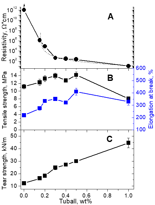
Fig. 23. Dependence of the electrical resistivity (A), tensile strength (B), and tear strength (C) of EPDM on the amount of Tuball SWCNTs. The dashed line in (A) corresponds to Kirkpatrick’s Eq. (3) with percolation threshold fc = 0.16 %.
As can be seen from Fig. 23, introduction of SWCNTs makes it possible not only to reduce the electrical resistivity of EPDM down to ~10 Ω∙cm but also improve its mechanical properties. The tear strength significantly improved while the tensile strength and the maximum elongation did not change noticeably at 1 % but at concentrations below 0.5 % some improvement was observed. The effects can be attributed to a good interaction between the rubber and SWCNTs despite the noticeable amount of introduced oil. Indeed, TEM images in Fig. 24 of the samples with SWCNTs in polymer after extracting petroleum oil with toluene show a thin layer of polymer adsorbed on the SWCNT bundles, which facilitates their good dispersion in the rubber compound.

Fig. 24, TEM image of SWCNTs dispersed in EPDM polymer after extraction of petroleum oil. Arrow points to the polymer coating the nanotube bundle.
At the same time, as can be seen in SEM images of Fig. 25 for EPDM with 0.3 % SWCNTs, the nanotubes form patches of relatively well distributed networks, which improve the strength of rubbers containing SWCNTs. The most pronounced is the tear resistance that almost linearly increases with the SWCNT concentration up to 1 %. The SWCNT network hinders the growth of cracks even for not perfectly homogeneous distribution of nanotubes. The increase in the maximum elongation at break can be explained by the plasticizing effect of the carrier medium (petroleum oil) from the SWCNT modifier. The tensile strength is more sensitive to the inhomogeneity of SWCNTs distribution and below 0.3 % the positive effect of adding SWCNTs outweighs, leading to strength increase, although not dramatic. Above 0.5 %, the inhomogeneity becomes detrimental.

Fig. 25. SEM image of EPDM with 0.3 % of SWCNTs.
The ‘Mystery’ of Doping.
Although Tuball SWCNTs are highly price competitive, there is always a need in various applications to minimize the amount for achieving the desired properties at optimal conditions. One such application relates to imparting conductive properties in thermoplastics. For example, low density polyethylene (LDPE) is quite inexpensive and is widely used for manufacturing various containers, dispensing bottles, wash bottles, tubing, etc. One method involves forming large containers by rotational molding and often antistatic properties of such containers is desired for use with flammable liquids.
As discussed above, one can achieve that by using SWCNTs and choose among the available Matrixes (see Tables S3 or S4) such as Matrix 605 based on PDMS with vinyl ends. The Matrix can be diluted down to 2 % on a three-roll mill and then mixed with LPDE powder on a laboratory knife mill to the desired final concentration. The outcome is very sensitive to the last step of mixing the LDPE powder with the concentrate. After the uniform conductive layer of the concentrate is formed on the surface of the powder grains (at the optimal mixing time), further mixing causes reagglomeration and gradual decomposition of this layer into individual fragments that are not interconnected, which leads to a strong resistance increase. As Fig. 26A illustrates, for our conditions, the optimum mixing is at 1.5 min.

Fig. 26. A. Resistivity of 0.01 % SWCNTs in LDPE samples prepared by rotational molding as a function of the mixing time in a knife mill. B. Conductivity of LDPE samples prepared by rotational molding with different concentrations of SWCNT and with Zn(NO3)2 or FeCl3 dopants (20 % with respect to SWCNTs). The lines represent Kirkpatrick’s Eq. (3) with σpristine =2.5(c-0.0090)2.4, σZn(NO3)2 = 2.5 (1.2*c-0.0090)2.4, and σFeCl3 = 2.5 (1.7*c-0.0090)2.4.
For that optimal protocol, the concentration dependence, presented in Fig.26B, corresponds to Kirkpatrick’s Eq. (3) with the percolation threshold ~0.009 %. As discussed above, raw SWCNTs are typically represented by a mixture of approximately 1/3 metallic and 2/3 semiconducting nanotubes. The electrical resistance of the system is mostly given by the contact resistance between them, which can be minimized by doping [82-91]. The latter affects all nanotubes but the effect on semiconducting nanotubes is more profound and is obvious in depletion of the optical transitions between van Hove singularities. Nevertheless, doping eventually aligns the Fermi levels not only between semiconducting but with metallic nanotubes as well. The resulting reduction of a Schottky barrier at contacts leads to improving the electrical conductance for the same amount of nanotubes; the percolation threshold also decreases.
Because of the abundant p-type dopant oxygen, the n-dopants are less likely to survive over the long time and thus we focus on the p-type dopants. The choice of an appropriate donor that survives all the processing and delivers reproducible stable doping effect is not that simple as it should also be complementary to the dispersion method. Since the carrier in a Matrix modifier remains in the media after mixing, it also can and often does performs as a dopant [90]. When using a p-dopant, one should choose a carrier that is either neutral or p-doping; Matrix 605 carrier is among the ‘neutral’ ones. Among the acids and inorganic salts, which are all p-dopants, the degree of doping is defined by the polarizing ability of the metal cation and the counteracting effect of the anion [92]. The effect of doping can be assessed trough the optical spectra, and Fig. 27 shows that for three of such typical dopants, Mg and Zn nitrates and FeCl3. The strength of the dopants increases in that order, as can be seen in the increasing suppression of S11 and S22 transitions; in the case of ferric chloride both peaks are practically vanished. The effect from the acids is even more pronounced but their use is prohibitive in the discussed applications.

Fig. 27. Optical absorption spectra of 2 % SWCNTs in Matrix 605 carrier with different dopants (20 % with respect to SWCNTs) pressed into thin films.
The three dopant salts were introduced at the level of 20 % with respect to Tuball by dispersing dry SWCNTs in ethanol solution of a dopant for 3 days followed by complete drying at 125 oC with subsequent introduction in Matrix 605 and processing with LDPE identical to that with pristine Tuball. Doped SWCNTs indeed give improved conductance compared to pristine: at 0.01 % Mg(NO3)2 dopant gives 6 times increase, Zn(NO3)2 – by 8 times, and almost by 90 times - with FeCl3. The percolation curve for SWCNTs doped with FeCl3 in Fig. 26B illustrates that the same level of conductivity in rotationally molded LDPE can be achieved at practically half the amount of doped SWCNTs as compared to the undoped ones. In a simplistic model, the inclusion of 2/3 of semiconducting nanotubes should effectively reduce the percolation threshold by a factor of 3 but the degree of doping in Fig. 27 actually has not reached the perfect alignment of Fermi levels between metallic and semiconducting nanotubes. Besides, the positive effect on the level alignment from a high level of doping is counteracted by the likely negative effect on the charge carrier scattering by the dopants that may lead to increasing resistivity of the nanotubes themselves. Thus, the reduction of SWCNT concentration by cheap and robust dopants should be viewed as a good outcome.
Augmentation of thermoplastics by SWCNTs has potential applications by improving their conductive (antistatic) and mechanical properties. The means of optimal introduction for the two goals are not necessarily the same. The methods discussed in literature include solution mixing, melt blending, and in situ polymerization. Since the dispersion quality of SWCNTs in a polymer matrix dramatically affects both the mechanical and conductive properties of the resulting composite, much attention has been paid to their uniform distribution [55]. Among the basic dispersion methods, which are usually based on mechanical action [93-99], the most common are ultrasonic processing [17,100,101], three roll mill [102,103], ball milling [104,105], mixing with high-speed shear mixer [106], and extrusion [107-110].
We distinguish the methods into two primary categories and characterize further details accordingly. The SWCNTs can be introduced into neat polymer with an additional carrier in a form of Matrix concentrate, like those in Table S4, or without such carriers.
There are numerous applications where introduction of additional components into a polymer is undesirable or even prohibitive. In such cases, approaches based on dispersions in a carrier Matrix are not suitable and pure concentrates of SWCNTs in the polymer become the primary choice. There are two options in how it can be achieved. In the first option, simultaneous dissolution of the polymer and SWCNTs in a solvent is followed by removal of the solvent, while in the second, SWCNT solution is prepared in the monomer and is followed by polymerization with SWCNTs already well dispersed in it.
The latter case is particularly convenient for a single-monomer case, like polyamide-6 produced from ε-caprolactam (CL). Polymerization can be performed with water as a catalyst, which requires temperature close 240 oC for over 8 hours, i.e., hydrolytic polymerization to produce hPA6, or through using special catalysts and activators (such as, for example, C10 and C20P from Brüggemann) allowing to run anionic polymerization at reduced temperatures, 140-160 oC, which proceeds in less than 30 min, to make aPA6. Anionic polymerization is often run directly inside a mold and then it is referred to as reaction injection molding (RIM) [112]. Tuball disperses well in melted CL (Tm = 68oC) but high-quality dispersion requires ultrasound activation [112]. As Fig. 28A demonstrates, small amounts of Tuball significantly increase the viscosity of CL solution, which is helpful for RIM without fiber but makes the intrusion of the solution into a carbon fiber filled form problematic when the concentration of carbon fiber (CF) and SWCNTs are high. It also puts a limit on the highest SWCNT concentration that can be conveniently and uniformly dispersed this way in CL to less than 1%. As discussed above for liquid dispersions, ultrasound activation becomes inefficient at high SWCNT concentrations. This is not the only ‘inconvenience’ in working with aPA6. The anionic polymerization process is very sensitive even to trace amounts of water and oxygen [111,112] requiring strictly controlled environment for preparation of dispersion and its subsequent polymerization.
Nevertheless, as Fig. 28B and Table 5 show, solution with 0.3% Ultrapure Tuball can be injected into a mold with 30% long CF for successful polymerization, i.e., reaction injection molding, (RIM). The bending strength increases with approximate slope of 67 MPa/wt% but for 30% CF with 0.2 % Tuball (0.3 % with respect to the polymer) the slope exceeds 600 MPa/wt% and the total effect is greater than the sum of individual increases for the SWCNTs and CF alone, i.e., there is a synergistic effect [112].

Fig. 28. A. Viscosity of Tuball solution in caprolactam at 90oC as a function of Ultrapure Tuball concentration. B. Stress-strain curves for bending of 6 mm diameter RIM aPA6 rods with different amounts of Tuball and long carbon fiber extending through the whole sample.
Table 2 – Mechanical properties of aPA-6 with SWCNTs Tuball and long carbon fiber extending through the whole sample
Flexural Strength, | Max. Strain | Young Modulus | |
aPA-6 | 145 ± 5 MPa | 20 % | 3.0 GPa |
aPA-6 + 0.3% SWCNTs | 165 ± 5 MPa | 9 % | 3.5 GPa |
aPA-6 + 30% LCF | 455 ± 10 MPa | 3 % | 30 GPa |
aPA-6+0.2%SWCNTs+30%LCF | 585 ± 15 MPa | 4 % | 33 GPa |
A similar synergistic effect is observed when a compound containing CF and SWCNTs is produced via a masterbatch with a high concentration (10%) SWCNTs, as will be discussed later. Such masterbatches (MB) in PA6 can be produced via solution method or through hydrolytic polymerization of caprolactam.
The former is based on dissolving PA6 in NMP with the help of CaCl2 or LiCl salt and mixing in a desired proportion with separately prepared suspension of SWCNTs in NMP. After thorough mixing on a high share mixer, this dispersion is quenched in water, washed with copious amounts water, filtrated, and vacuum dried to remove residual NMP and water. Figure 29 A and B illustrates how NMP based 10% MB upon mixing with neat PA6 on an extruder to the desired concentration of SWCNTs improves the strength and modulus of the compounds. The strength is noticeably less than such for MB from hPA6. This is likely due to incomplete removal of trace amounts of NMP. It agrees with even lower strength for the compounds prepared directly from NMP solution to the final concentration.
In hydrolytic polymerization water is used as a catalyst and this eases the dispersion conditions allowing more effective and yet efficient means of SWCNTs dispersion such as using three roll mill (3RM) or ball mill. A mixture of SWCNTs with wet caprolactam in desired proportions mechanically mixed was polymerized at 240oC for 8 hours in a closed vessel and, after cooling down, was crushed into small pellets and washed in hot water for 8 hours to remove the unreacted monomers and water-soluble short oligomers. After filtration and drying in a vacuum oven at 100 oC, the resulting masterbatch (typically 10 %) can be compounded to the desired concentration with neat PA6 or PA6 with addition of carbon fiber (CF) or glass fiber (GF). This method of preparation of MB is obviously giving much better improvement of the mechanical properties of composites, which is likely due to a better control of the undesired residue of NMP and more even distribution of SWCNTs in the resulting compound. The latter is clearly visible in the optical images of hot-pressed compounds in Fig.29 C, D, where SWCNT bundles are practically unrecognizable in 0.3% compound obtained from hPA6 masterbatch, while in the analogous compound obtained from masterbatch prepared through NMP solution the bundles are clearly visible, although of very small and thin aggregates.

Fig. 29. Ultimate strength (A) and tensile modulus (B) for injection molded samples of PA6 compounds with different amounts of Tuball. The ‘MB’ samples were prepared by diluting original 10% masterbatch, either via hydrolytically polymerized caprolactam, hPA6 (green diamonds), or via dissolution in NMP (black squares). Direct preparation of the final compounds by dissolution in NMP is given by blue circles. Optical images of 0.3 % compounds hot pressed into thin films are shown in C (from hPA6 MB) and D (from NMP MB); the bar is 20 μm.
Even though the approach for preparing MB based on the NMP solution method appears inferior here compared to the hPA6 masterbatch, it is still very appealing in the cases where polymerization of the monomers with SWCNTs is not sufficiently developed yet, such as other polyamides, e.g., MXD6, PPA. The currently limiting factor for applying polymerization with SWCNTs in other systems is the quality of SWCNT dispersion in the monomers, which affects the quality of dispersion in the resulting polymer and gives the solution method approach a competitive edge.
When comparing the data for the effect of Tuball on mechanical properties of PA6 in Fig. 29, one can see that the most dramatic distinction is in the strength while the modulus is very similar and close to linear for all three methods. The slope for the modulus for hPA6 MB is close to 1.2 GPa/wt% in the initial range up to 1%. The strength within first 0.1% rises with almost 80 MPa/wt% slope and then significantly slows done to 20 MPa/wt%. These values are fairly close to the theoretically expected based on the law of proportions of Eq.(11). Using the SWCNT density, ~1.4 g/cm3, and the density of PA6 1.14 g/cm3, dσc/dVf becomes close to 100 MPa/v%. In a similar manner, the modulus’ slope is dEc/dVf ~1.5 GPa/v%, slightly below the expected ~2 GPa/v%.
The synergistic effect is llustrated by how the mechanical prepoerties altered in the composite of PA6 with 10% carbon fiber by addition of Tuball, see Fig. 30. The slope for the modulus is now dEc/dVf ~2.8 GPa/v%, i.e., almost twice as high compared to PA6 without CF.

Fig. 30. Tensile strength and modulus for injection molded samples of PA6 composites with 10 % of CF and different amounts of Tuball introduced using hPA6 masterbatch.
It would be next to impossible to cover all possible applications of Tuball, some of which are under development, others have limited scope or simply were missed. There are some that would be difficult to characterize into the described above categories, but one can crudely divide it into antistatic applications (improvement of conductive properties) and improvement of mechanical properties.
An example of antistatic/conductive application is antistatic floor coating that contains curable polyurethane resin and Tuball single-walled carbon nanotubes in the amount of 0.001–0.1 %, which was reported to allow achieving surface resistivity from 109 to 105 Ohm/sq [113]. In another example, colored thermoplastic composite materials, such as polypropylene (PP), polyethylene (PE), ABS, polystyrene, and others upon introduction of 0.001–0.2 % Tuball single-walled carbon nanotubes gains reduced resistivity ranging from 1010 to 106 Ohm·cm [114]. Because of low Tuball concentrations, such conductive composites can retain color of the added dye. Polypropylene (PP) fibers can also be rendered conductive by adding Tuball even after drawing. It was reported that PP fibers with 0.1% and 0.3 % of Tuball have resistivity of 108 and 102 Ohm·cm, respectively [115]. The strength improvement was not observed there but the lower concentration option was suitable for getting the fibers colored with a dye, i.e., can be used in antistatic textile applications. Alternative means of achieving antistatic properties of textiles was demonstrated by coating fabrics with a diluted aqueous solution Tuball Coat E or specially designed aqueous dispersion of [116]. The resulting 20-200 μm thin layer with ~0.2% of Tuball gives 103-107 Ohm/sq surface resistivity to a fabric that could withstand over 10 washings. An unusual antistatic application was reported in [116], where introduction of < 1% of Tuball (via Tuball Coat E H2O) into high explosives such as trinitrotoluene, pentaerythritol tetranitrate, benzotrifuroxan makes them conductive, which reduces the sensitivity of explosives to static electricity. It increases safety of explosives during production and application and should reduce the number of accidents.
Much higher conductivity is required for protecting aircrafts from lightning strike. Authors of [118] showed that Tuball paper, i.e., a buckytape with 10 or 25% of PVDF is comparable to the expanded copper foil in that regard. When placed on the top of carbon fiber reinforced polymer before fabrication of flat panels it improved the surface electrical conductivity by 88 times and the volume conductivity - by 3 times. The buckytape also improved the impact resistance and thermo-mechanical properties of modified laminates. The buckytape is a commercial product of OCSiAl and produced using Tuball Batt NMP with nonstandard concentration of PVDF.
Examples of mechanical improvement of materials by Tuball extend quite far. It includes unexpected positive effect even on glass. Coating of glass vessels (bottles) during cooling with a thin (5-50 nm) layer of tin dioxide or titanium dioxide containing 0.05-1 % of Tuball (via one of the types of Tuball Coat E) improves their strength by up to 33% [119]. Modification of asphalt concrete mixture composition by Tuball in the amount as low as 0.005–0.5% with respect to bitumen improves the performance characteristics of asphalt concrete, such as an increase of its softening temperature and the corresponding high-temperature rutting resistance [120]. Strengthening of metals by SWCNTs has also been reported. In [121] carbon nanotube reinforced copper composites Cu/CNTs have shown the tensile strength improvement in a diameter dependent manner, almost inversely proportional to the diameter. As a result, the highest improvement of the ultimate strength, ~ 3 times compared to neat Cu, was observed for for 4 vol.% DWCNTs/SWCNTs with diameters < 3 nm. The electrochemical deposition method of Cu/CNTs production is not convenient for scaling up. The casting of powdered SWCNT/Al mixtures is more suitable but shows more modest improvement of the ultimate tensile strength of cast metal -- by 9% for A5 aluminum reinforced with 0.01% Tuball [122] and by 15% for AD0 aluminum reinforced with 0.5% Tuball [123]. Tuball additive also helps better retaining the strength after annealing.
We have demonstrated that SWCNTs have a broad range of commercially viable applications, from batteries to thermostes, and thermoplastics. Many other applications are likely waiting for fruition and OCSiAl has developed a series of intermediate solutions as liquid and solid dispersions of Tuball that can help in expansion of such applications. Some of these intermediates are employed in numerous applications by OCSiAl and other companies and research groups. We believe that the abundance of high quality SWCNTs in the form of Tuball and a number of versatile intermediates offered by the company should recruit more scientists and engineers into employing this really amazing material into a broad range of applications.