Choosing between dissipative and conductive in ESD-control flooring: a comprehensive review of ANSI/ESD S20.20-2021
Discover the essential elements of ESD (electrostatic discharge) flooring and gain insights into achieving optimal ESD protection and mitigation. In this article, we debunk common misconceptions, explore the significance of resistance levels, and shed light on the latest material advances that address industry challenges. Join us as we delve into the world of ESD flooring to create specifications that strike the perfect balance between functionality, aesthetics, and ease of installation.

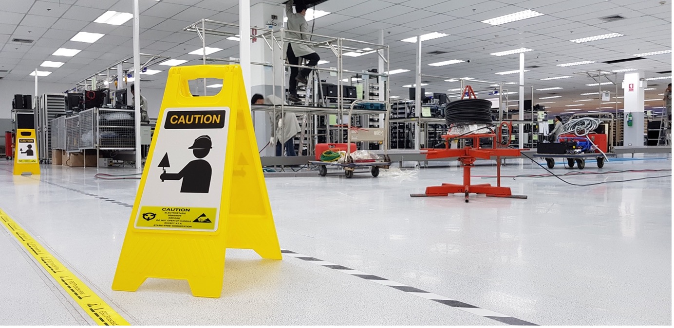
Beyond the realm of electronics manufacturing, the demand for ESD flooring extends to encompass diverse sectors such as call centers, data hubs, and warehouses utilizing autonomous vehicles. However, the industry faces challenges due to the complexity of design and the risk of insulative spots associated with ESD-control flooring installations. Navigating these hurdles, ESD flooring specifiers find themselves contending with a multitude of standards and regulations, with ANSI/ESD S20.20 emerging as the most prevalent. Within the framework of these standards, a certain degree of confusion arises concerning the optimal resistance levels for ESD-control floors. This confusion can lead to misconceptions, resulting in the imposition of resistance thresholds that, in the best scenario, add complexity and affect aesthetics, or in the worst cases, pose risks to the safety of workers.
To overcome these challenges and ensure optimal ESD control, understanding of the ANSI/ESD S20.20-2021 standard and resistance levels is crucial.
What is the real required resistance level for safeguarding electronic equipment?
The ANSI/ESD S20.20-2021 standard, from the EOS/ESD Association, specifically concerns epoxy coatings for ESD-control flooring. Here are three key insights for every specifier dealing with S20.20-2021.
1) S20.20-2021 is a program, not a flooring standard
ANSI/ESD S20.20-2021 significantly shapes ESD-control environments, but it isn’t merely about flooring. It outlines an ESD-control program covering various aspects, including flooring.
The purpose is to lay out “requirements necessary to design, establish, implement, and maintain an Electrostatic Discharge (ESD) Control Program for activities that manufacture, process, assemble, install, package, label, service, test, inspect, or otherwise handle electrical or electronic parts, assemblies, and equipment susceptible to damage by electrostatic discharges greater than or equal to 100 volts Human Body Model (HBM).”
When specifying flooring, remember that the ultimate measure of success is not achieving a certain resistance threshold across the floor but preventing the accumulation of charge leading to a discharge of 100 volts or more from a person. This is the compliance yardstick. The floor’s resistance to ground matters, but only within this larger context. ANSI/ESD S20.20-2021 specifies flooring resistance under 1×10^9 Ω at all points.
2) Dissipative or conductive?
Commonly, flooring with 10^7 to 10^9 Ω resistance is seen as dissipative, while below 10^5 Ω is conductive. This led to the convenient 1 megohm (1×10^6) threshold for ESD-control flooring specs.
Nonetheless, correctly installed 10^7 to 10^9 Ω flooring meets S20.20-2021’s charge accumulation criteria while avoiding extreme conductivity risks. Aim for the lower end of the static dissipative range, steering clear of static conductive. A fixed 1 megohm threshold is unnecessary; focus on resistance below 10^9 Ω, factoring in walking voltage tests.

3) Does more conductivity necessarily mean better?
The standard often pushes for 1 megohm resistance. Yet, two scenarios complicate things. First, aiming for an exact 10^6 Ω target is tough due to resistivity’s logarithmic nature and variations with temperature, humidity, and material dispersion.
This leads to the second complication—the belief that lower resistance is always better. Remember, the aim is to prevent electrostatic charge buildup leading to 100–volt discharges. Given resistivity’s logarithmic nature, a 10^5 Ω threshold increases the likelihood that a floor contributes to a shock hazard.
Rather than maximal conductivity, focus on reducing levels to safely meet S20.20’s requirement of no 100–volt discharges. This means resistance under 10^9 Ω.
Achieving ESD protection with minimal material and zero insulative spots
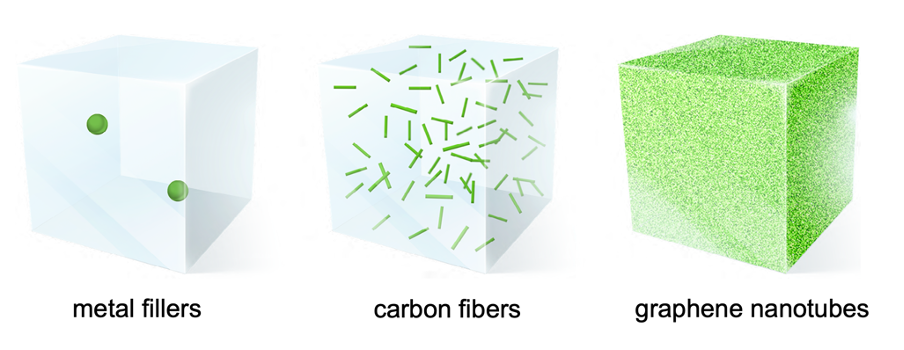
Conventional conductive materials like carbon black, tin oxide, and metal fibers bring complexities—difficult installations, limited color control, hot spots, and “orange peel” risks. This is due to loading rates (generally 6% to 20%).
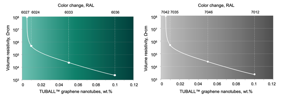
A revolutionary option emerges: graphene nanotubes, such as TUBALLTM from OCSiAl. These nanotubes, also known as single wall carbon nanotubes, have high aspect ratios and form effective conductive networks with minimal loading (0.01–0.05 wt.%), providing greater control over color and finish, and avoiding dark shades in the final coating. This cuts costs and reduces environmental impact. What’s more, such ESD floors can even be used without conductive primer.

Picture 1. A comparison of conductive agents. At loading rates of approximately 0.01%, only graphene nanotubes are able to create a 3D conductive network.

Picture 2. Electrical conductivity and variety of colors provided by TUBALLTM graphene nanotubes.
Embracing the potential of graphene nanotubes in the flooring sector, coupled with specifiers’ enhanced understanding of the resistance benchmarks for S20.20-2021 adherence, makes it possible to overcome existing challenges. Industries such as cleanrooms, pharmaceuticals, and automotive applications stand to benefit from these material innovations.
References:
1. ESD Association: https://www.esda.org/store/standards/
2. Ibid.
3. New perspectives in SWCNT applications: Tuball SWCNTs. Part 1. Tuball by itself—All you need to know about it. Carbon Trends (2022). DOI: 10.1016/j.cartre.2022.100175